Automated Pick and Place Prototype
The Goal:
TLDR; I learned how to validate designs, iterate quickly and build something real.

Move objects from a loading area onto a conveyor belt with high speed and high compliance. We wanted to move objects of all shapes and sizes, ranging from 3D printed benchy’s, to crushed cans, pipe fittings, and scrap pieces of wood.
Design Objectives
1. Design for Speed
The goal was to move 1 object every 10 seconds, by moving multiple objects within a single pick and place cycle
2. Design for Compliance

The goal was to move objects of various sizes with a combined total payload of 100g
Individual Project Contributions
Concept Design
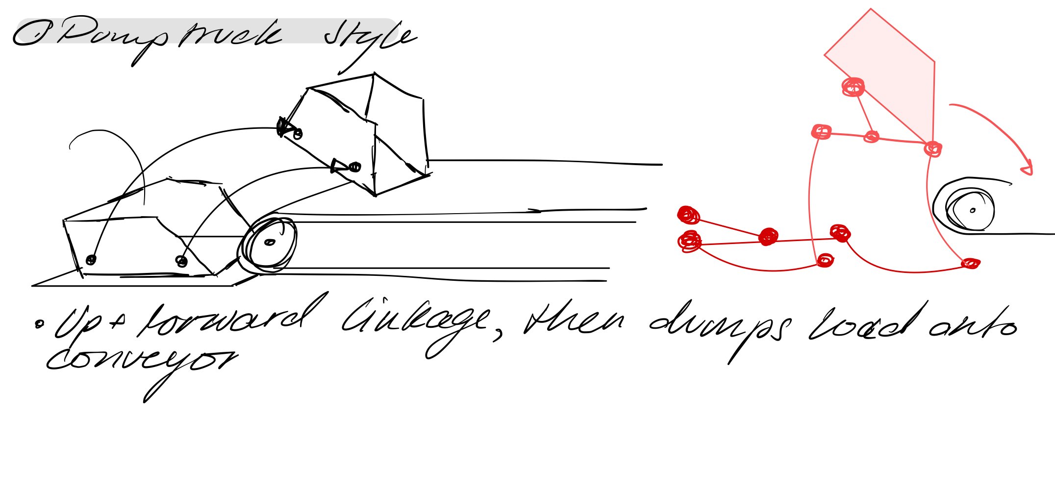
I came up with the concept of a four bar linkage with offset lengths to dump objects on to the conveyor.
This design was capable of delivering high quantities of objects at once, and the open dumper design allowed objects of various sizes to be loaded.
4-Bar Linkage Modelling
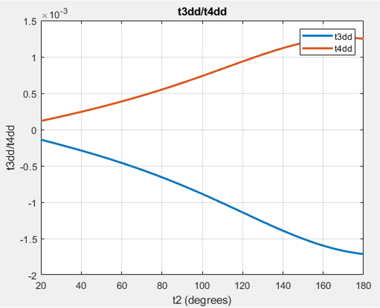
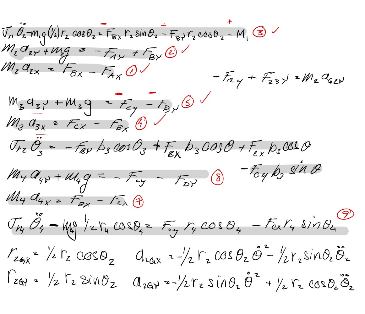
A key aspect of this project was determining the amount of torque required to lift the desired objects up on to the conveyor. To do this, I wrote a script to simulate the linkage in MATLAB.
First I derived the force and acceleration equations for each joint of the linkage.
Then, I used MATLAB to solve these equations for the desired range of motion of the linkage.
This yielded graphs for joint forces, angular accelerations, and importantly the driving torque as a function of angle.
Adjustable Torsion Spring Mechanism
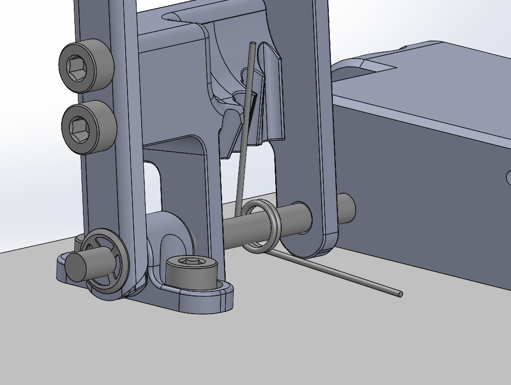
Object Retention Mechanism


The required driving torque to move the 100g load at a constant angular velocity was determined to be 0.812N-m.
Mechanical Design and Layout


The MG995 servos we had available for this project had a stall torque of 0.822N-m. This leaves little to no margin for error when lifting the 100g load!


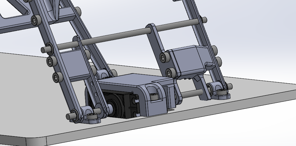

Adding a 1.5X factor of safety onto the design, the goal was to now spec components to create 1.218N-m of driving torque. Instead of adding an additional servo which would increase cost and complexity, I specced torsion springs to increase the applied torque.
Each torsion spring provides 0.1N-m of torque. Adding four springs to the assembly along with the servo provided 1.233 N-m of stall torque.
This is sufficient torque to move the required load!
My final main contribution to the project was mechanical design and layout of the mechanism. The mechanism was modelled in Solidworks. The key design features are listed below.
This component allows torsion springs to be easily swapped out and replaced allowing the spring tension to be quickly tuned.
This simple component moved with the mechanism to keep objects from falling out prematurely during motion, and acting like a funnel to center objects on the conyeyor in the up position.

I also designed everything from the servo housing, to the dumper box, to the aluminum links


Overall Design
The Final Product


What I Learned
Brushed up on modelling rigid linkages and Mechanics of Machines.
Learned to start manufacturing early and expect problems with the first prototype. Leave time to redesign and remake parts.
Add as much adjustment to designs as possible. Unless parts are being professionally machined, there will always be issues with tolerances.
Check for interferences in CAD and perform sweep studies to check clearances.