Carbon Fiber Hyperloop Monocoque
What is Hyperloop?
In a nutshell: A maglev train in a vacuum tube to reduce frictional losses
Commercial Feasibility? Questionable.
A fun challenge for Design Teams? Yes.
The Problem
The previous version of the pod had a welded tube aluminum chassis weighing about 45 lbs. When speed and efficiency are key to success, mass means friction, and friction is slow. With the next-generation pod, my goal was to eliminate as much weight as possible while maintaining similar strength to the previous frame.

Conceptual Design
My design process started with concept sketches. I knew I wanted the frame to drape over the I-beam track in a C channel shape. This was for 2 reasons.
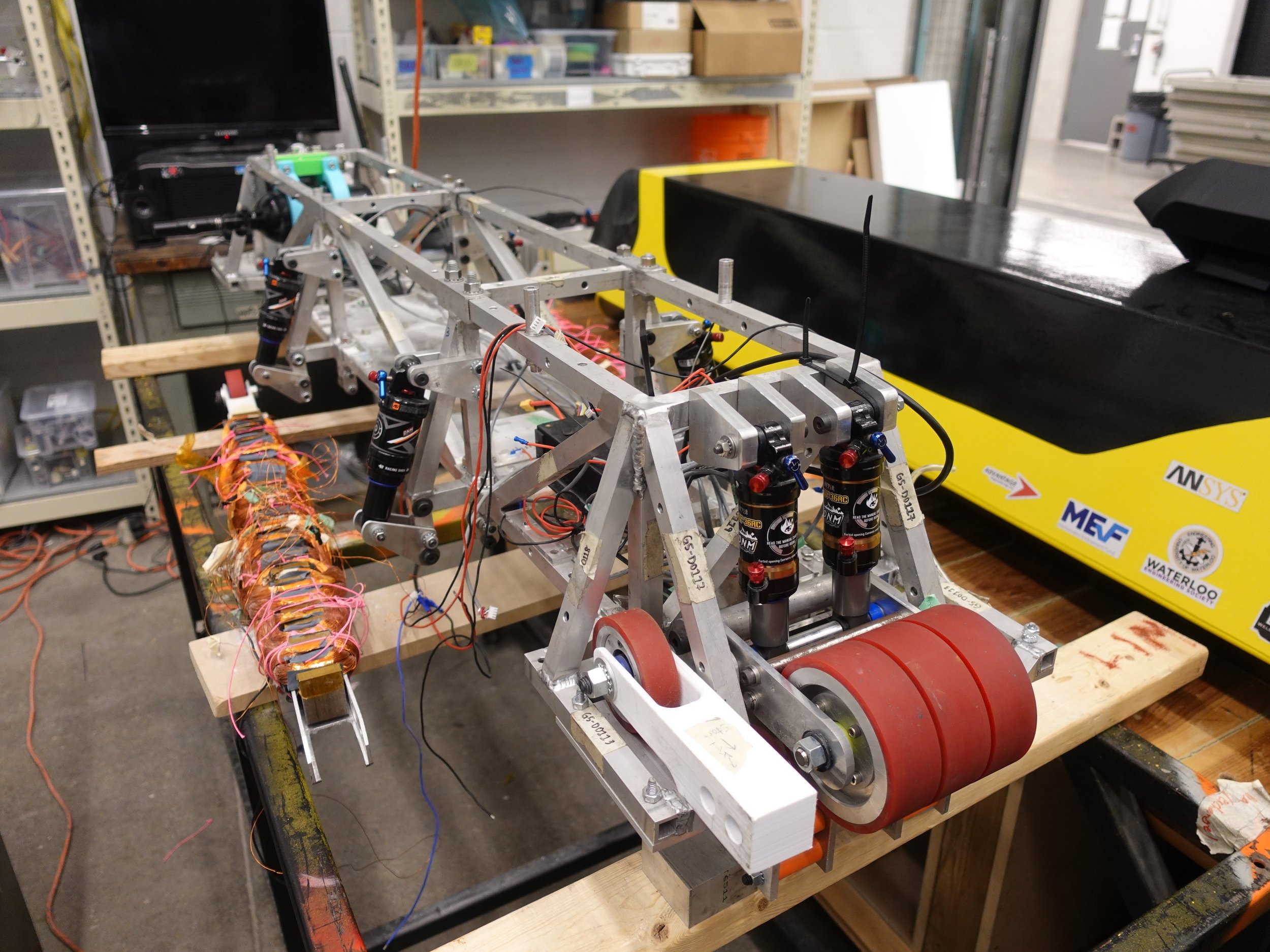
The linear induction motors on the pod sit in between the two flanges of the I-beam. This C shape provides a stable mounting surface for the motors and other components
The C-shape was simple to manufacture out of carbon fiber and provided a larger area moment of inertia to resist bending.


Mechanical Design & DFM
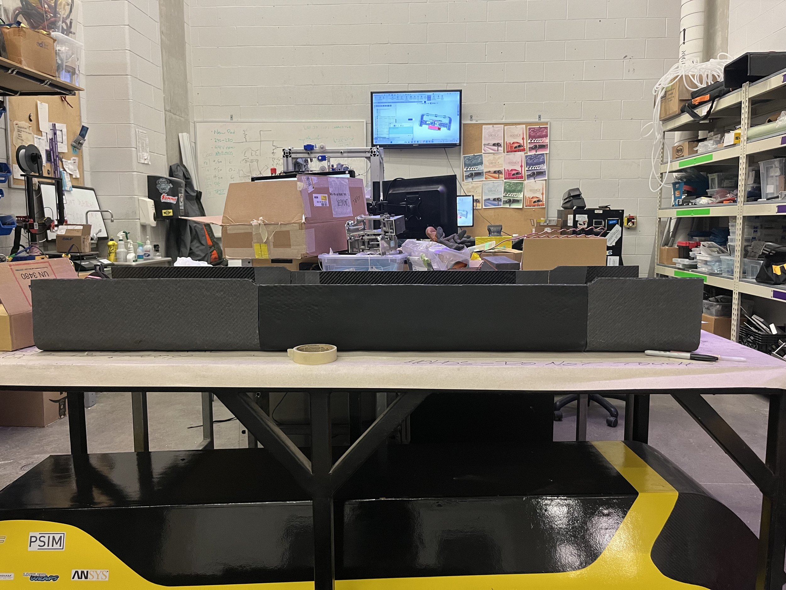
I designed the monocoque to be a simple C-channel shape to simplify manufacturing and mold making.
By eliminating complex curves, the mold could be made by hand instead of on a CNC and the carbon could be layed-up in one continuous peice.

Composite FEA Analysis
The initial plan was to construct the carbon chassis as a single 6 foot piece of carbon fiber. After the attachment criteria and constraints had been set, cut-outs and mounting holes were added. To validate the chassis, the structure was modelled in ANSYS Composite PrepPost.
First in ACP Pre, the geometry shell was imported, meshed, and 6 layers of 621MPa AXIOM AX-5201 12K Pre-Preg were imported as material layers around a 3/8th in plastic honeycomb core within the stack-up properties.
Then, rosettes were placed in the regions of the frame I predicted would see the most load. A 3 point bending scenario was modelled in this case. For this scenario, rosettes were placed on the outer most plies concentrated on the middle of the frame.
Then I plugged the ACP Pre configuration into a static structural model of a 3 point bend scenario. The results were then imported into the Composite Failure tool to determine the stress in each ply. The maximum tensile stress in this scenario equated to a 6.2x safety factor at the center of the chassis.
The deformation of the frame was also modeled to understand the required clearances on underframe components. A maximum deformation of 0.8mm was estimated at the center of the frame.


Testing and Development
I had never designed for or manufactured with carbon fiber before starting this project. I learned the basics of mold design, mold release methods, layer orientations, and the manufacturing limitations of designing with composites.
To start, I made a small panel made up of 3 ply’s of prepreg, oriented in a 45°, 90°, 45° layer pattern to achieve quasi-isotropic properties. A layer of 1/2" Nomex core was then placed between the sets of layers, for a total of 6 layers of carbon fiber.

Putting the panel through it’s paces.

Peel-ply layer. Intentionally made rough for use with adhesives.

Carbon panel in the vacuum bag. Thermistors were placed on the sample to monitor the temperature throughout the cure.

Mold side. Release film creates a smooth, shiny finish.

A student-built curing oven was used to cure the carbon panel to 95C for approximately 6 hours.
The panel cured as expected. This sample proved feasibility of manufacturing a final frame prototype.
The panel was also extremely strong (as you can see from our very scientific bend test).
The next step was to lay-up the hyperloop frame.
Set-backs
The initial design was planned to be layed up and cured at a custom composites manufacturing shop in Markham, Ontario. The monocoque was designed to be manufactured out of 64” continuous sheets of pre-preg carbon fiber. It would then be cured under vacuum for 3 hours in a 120C autoclave.
With only 3 months before the competition, our composites manufacturing partner pulled out of the sponsorship agreement due to a new contract they had recently taken on. With no way of curing our current monocoque design, it was back to the drawing board.
Design Modification
Within my university, I had the capability of curing small composite pre-preg parts (generally for testing purposes) in a student made curing oven. However, I was contrained to lay-ups 34” in length due to the size of the oven. Due to this constraint, I decided to split the monocoque into 3 parts.
I came up with 2 concepts for attaching the pieces together.
1. Bonding the parts together with additional layers of “wet” carbon fiber.

This method would involve laying additional strips of carbon fiber fabric over the seams of the pieces, then applying epoxy to bond the monocoque sections together.
This method was identified as high risk as the strength of the connection would be entirely dependent on the shear force of the epoxy adhesive. There was no way of overlapping separate sheets of fabric like in a typical composite manufacturing process.
2. Mechanically attaching segments with plates and fasteners.

This method involved mechanically attaching the parts with a series of fasteners. This method was much simpler to model and predict as it is not dependent on the quality adhesive application and curing. Instead, the strength of the joint comes from fastener shear strength and clamping fricton of the joint.
I put together a brief decision making matrix to decide on the modification direction. The clear winner was to mechanically attach the segments.

Structural Validation
I modelled a design in Solidworks consisting of 6 sets of plates sandwiching the carbon segments together:

Design Considerations:

1. The shear load of each fastener must be distributed into the carbon layers.
To do this I designed aluminum inserts that were epoxied into predrilled holes. The inserts were designed to take the bearing load of a fastener and distribute the force into the outer carbon fiber sheets of the monocoque. I machined the inserts on a manual lathe out of AL 6061-T6.
To estimate the allowable force of each insert, I referenced NASA 19880005638: Simplified Procedures for Designing Composite Bolted Joints.


A carbon fiber joint can fail in one of 5 ways (as shown). There are 5 design variables I altered to create a joint that failed in the desired fashion.
e: Edge distance. A small edge distance increases the chances of shear-out failure.
w: Width/fastener spacing. A small width increases the chances of net-tension failure.
d: Insert diameter. A larger diameter distributes the load across a larger compressive area decreasing the chance of local bearing failure.
t: Ply thickness. More plies increase the contact area to the insert decreasing the chance of local bearing failure.
By subbing in the design parameters of the plate joints, I calculated the Margin of Safety (MOS) of each failure method.
Since the monocoque design only included 3 plies of carbon, the cured thickness (t) became the limiting factor of the insert. For this reason, with the given with (w) between fasteners and the edge distance (e), the inserts were predicted to fail in local bearing at roughly 3850N.

2. The bearing force in each insert must be less than the failure strength of the insert.
I created an FEA model of the 3 segments of the frame and simplified geometry of the fasteners and plates. I treated the carbon segments as infinitely rigid to speed up meshing and analysis. This assumption was made due to the large (6.2x) margin of safety in the ANSYS ACP simulation. I assumed that the insert tensile load (above) would be the limiting factor of the design.
I then added pin connectors between plates and the infinitely rigid carbon segments. As a simplified model, roller supports were added on both ends to constrain the model in the upward direction. A point load of 1200N was inserted at the center to create a 3-point bending scenario. This correlated to the 120kg of additional components the team planned to add to the pod. The heaviest components (motor controller, motors, etc.) were placed roughly central on the pod to balance the center of mass.

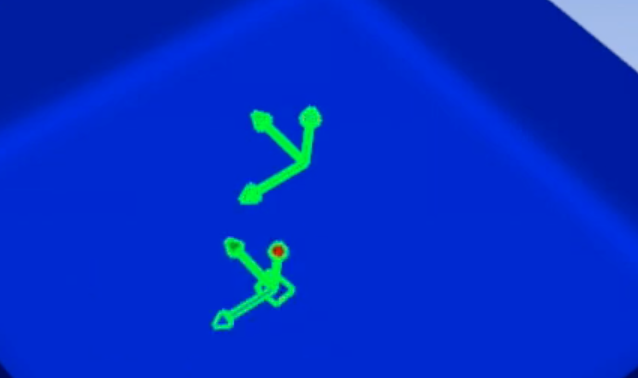
As expected, the results exceeded the requirements. The maximum stress within the plates occurred in concentrated regions where the pins were in contact.

The most important result of this analysis was the maximum shear load in each pin. This value correlates to the calculated maximum shear load for each insert.
The calculated failure value for each insert was ~3850N, well above the maximum simulated load of 241.44N.


Physical Testing
To verify the calculated insert failure results, I created various tensile test samples. I laid up a test batch of carbon, drilled holes, and epoxied inserts.
I then made a quick jig out of scrap aluminum that would load the pinned insert in a double shear configuration.

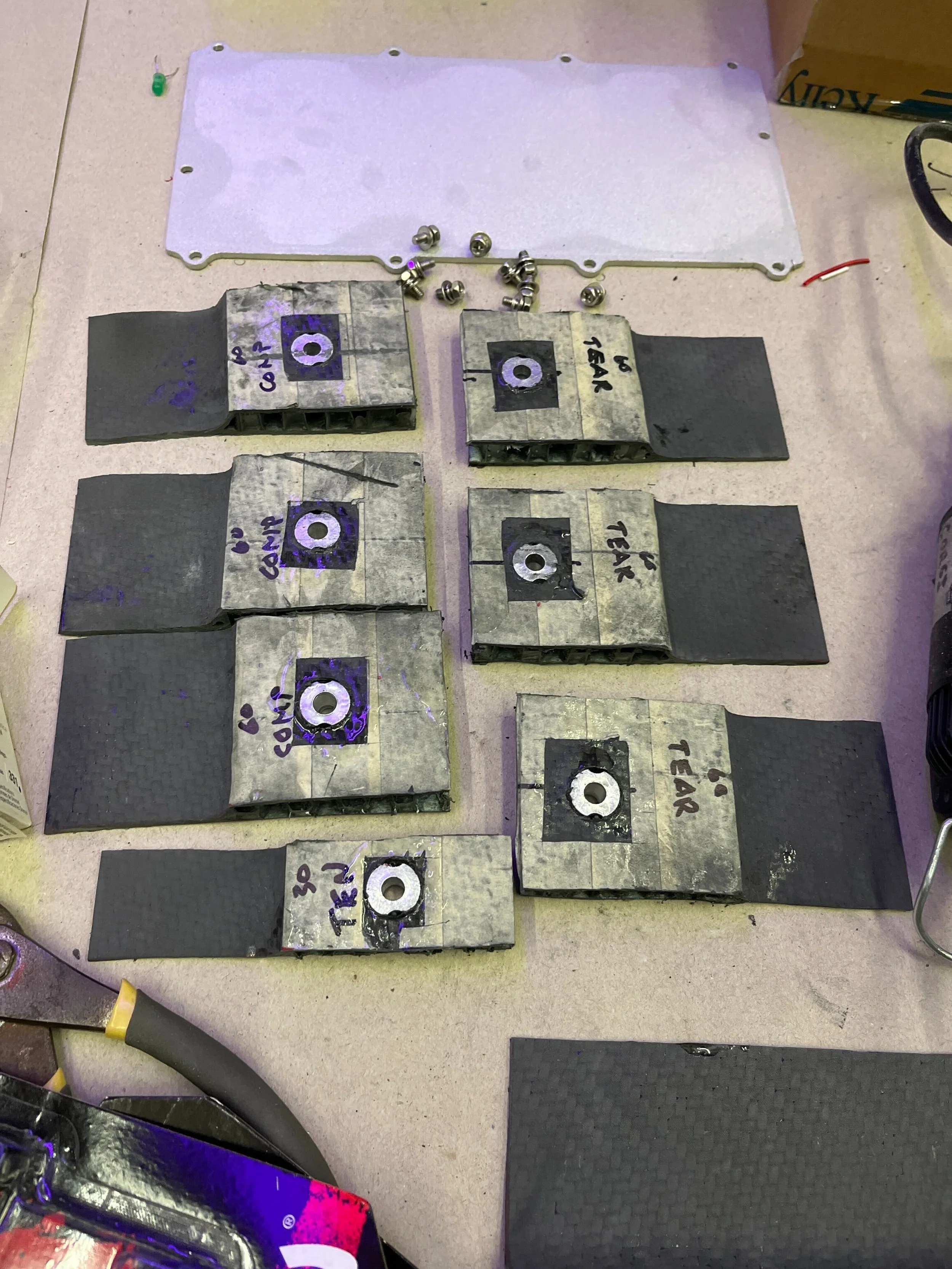

I then tensile tested 9 samples in my schools materials lab. Below is a video of one of the tests. The snaps and pops are pretty satisfying.