Ergonomic Retention Clip Tool
Toyota Motor Manufacturing Canada
The Problem
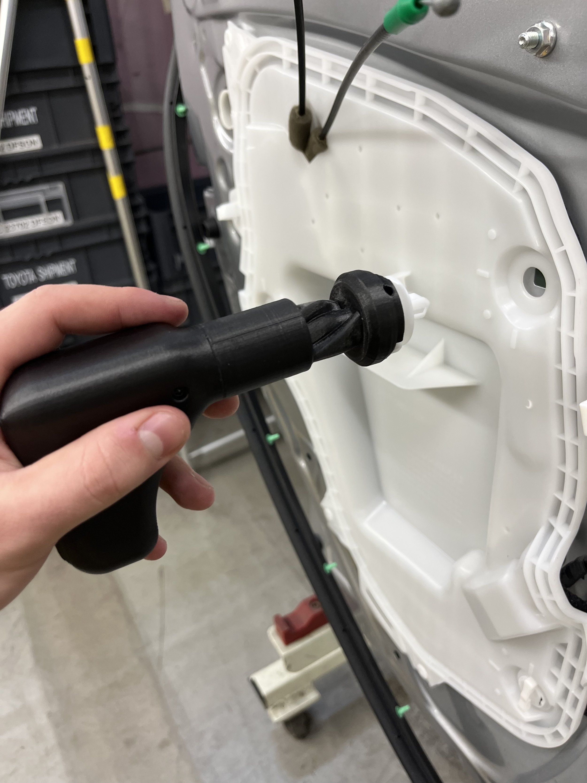
3 plastic retention clips had to be inserted to attach the close-out panel to all RAV-4 doors. At a 28-second cycle time, over 8 hours, this is roughly 3,085 clips installed per person, per day.
These X-shaped clips are first inserted into the door, then twisted 45 degrees to lock the close-out panel in place. Initially, this motion was done by using three fingers to hold the clip and twist it into place.
This poses a major ergonomic issue. This install took 4.1kgf of linear force, exceeding the finger push target of 3kgf (TEMA, 2003), and resulted in repeated non-neutral wrist posture.

“>45° pronation/supenation is considered a non-neutral posture and results in ergonomic risk to the forearm.” (Mukhopadhyay et al., 2007)
“Any non-neutral wrist postures, 45° of flexion, 30° of extension and 20° of deviation results in ergonomic risk to the hand.” (Keir et al., 2007)
The Goal
Distribute the 4.5kgf installation force into the palm of the hand. This would meet the 1 handed push target of 7kgf (TEMA, 2003).
Eliminate the 45° wrist pronation during installation to conform to Keir et al.
Step 1: Question the Constraints
Q: Why do the clips need to twist? A: An existing clip with the same retention requirements would exceed the 7kgf install requirement! NVH/rattle risks with a lower retention.
Q: Can I redesign the clip? A: Clip is standard across many Toyota vehicles. Cost prohibitive!
Q: Can I redesign the close-out panel to include a hook & swing or other retention features?
A: Requires new injection molding process and modifications to inner panel stamping dies. Cost prohibitive until a complete vehicle redesign!

Can I improve the manufacturing process to eliminate the risk? YES!
Step 2: Inspiration and Requirements
I took inspiration from the Yankee screwdriver mechanism that used a spiral slot around a shaft that would allow a ball bearing to guide the rotation of the screwdriver shaft.
One difference in the case of the clip was the tool still needed to have sufficient friction within the mechanism to allow for initial insertion before twist.


The tool also needed to precisely control the clip rotation within 42-48° for repeatable install.
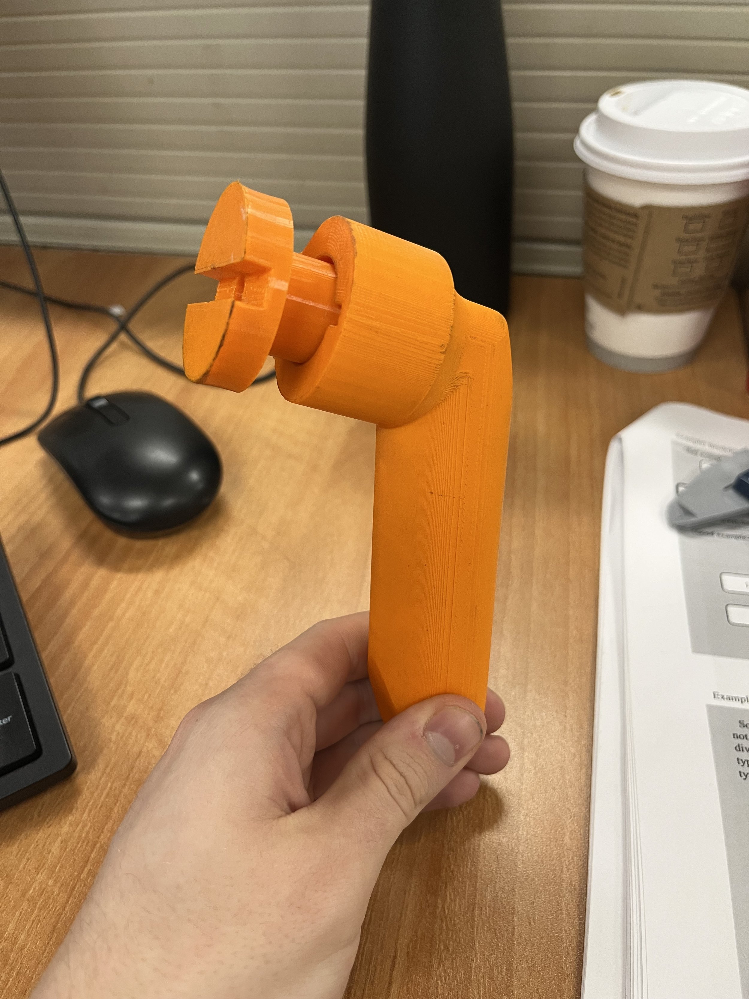
Step 3: Designing a Tool
I went through 6 iterations with this tool, tuning factors such as insertion force, handle shape and ergonomics, and clip retention.


There were a few criteria that required some prototyping and fine-tuning to get right.
1. Spring tension. The spring had to be strong enough to return the mechanism to it’s original position, yet flexible enough to conform to insertion forces.
2. Push force/friction. The draft of the helix mechanim had to be gradual enough to allow for a smooth push stroke and return stroke, but not too long such that the operator had to extend their arm.
3. Clip retention. The tool had to be designed such that the clip could be easily placed into the head, yet easily released post install.
4. Handle ergonomics. I trialled the different tools with various operators on the assembly line (the customers) and collected their feedback.
The tool took 6 iterations over ~2 weeks of trials to get to a state where it could be used consistently on a fast-paced moving assembly line.
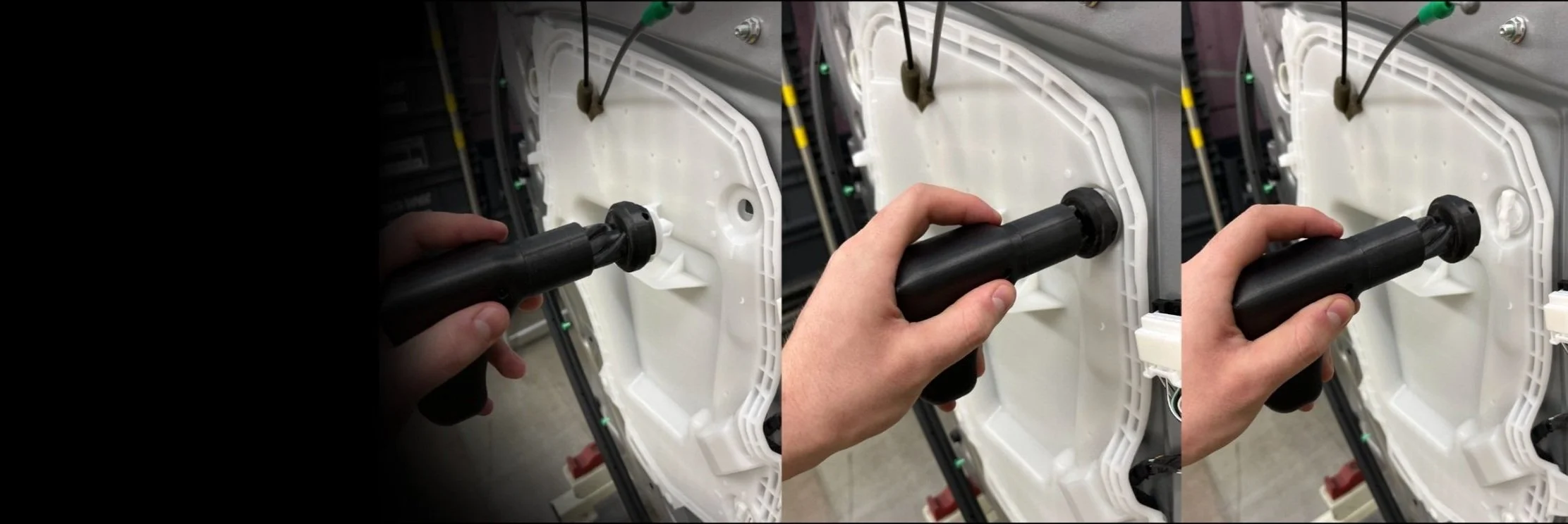
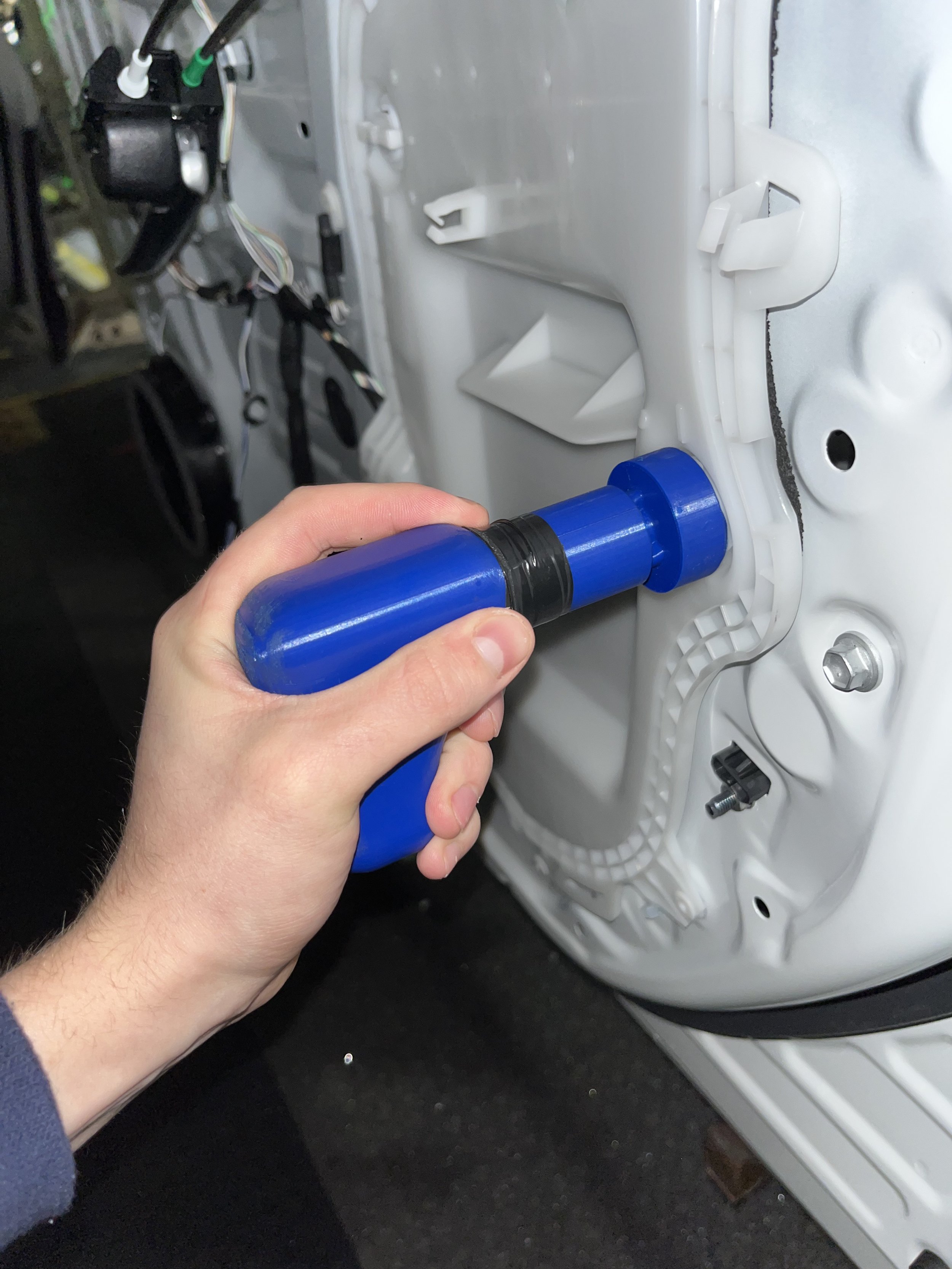
Step 4: The Final Tool
Results


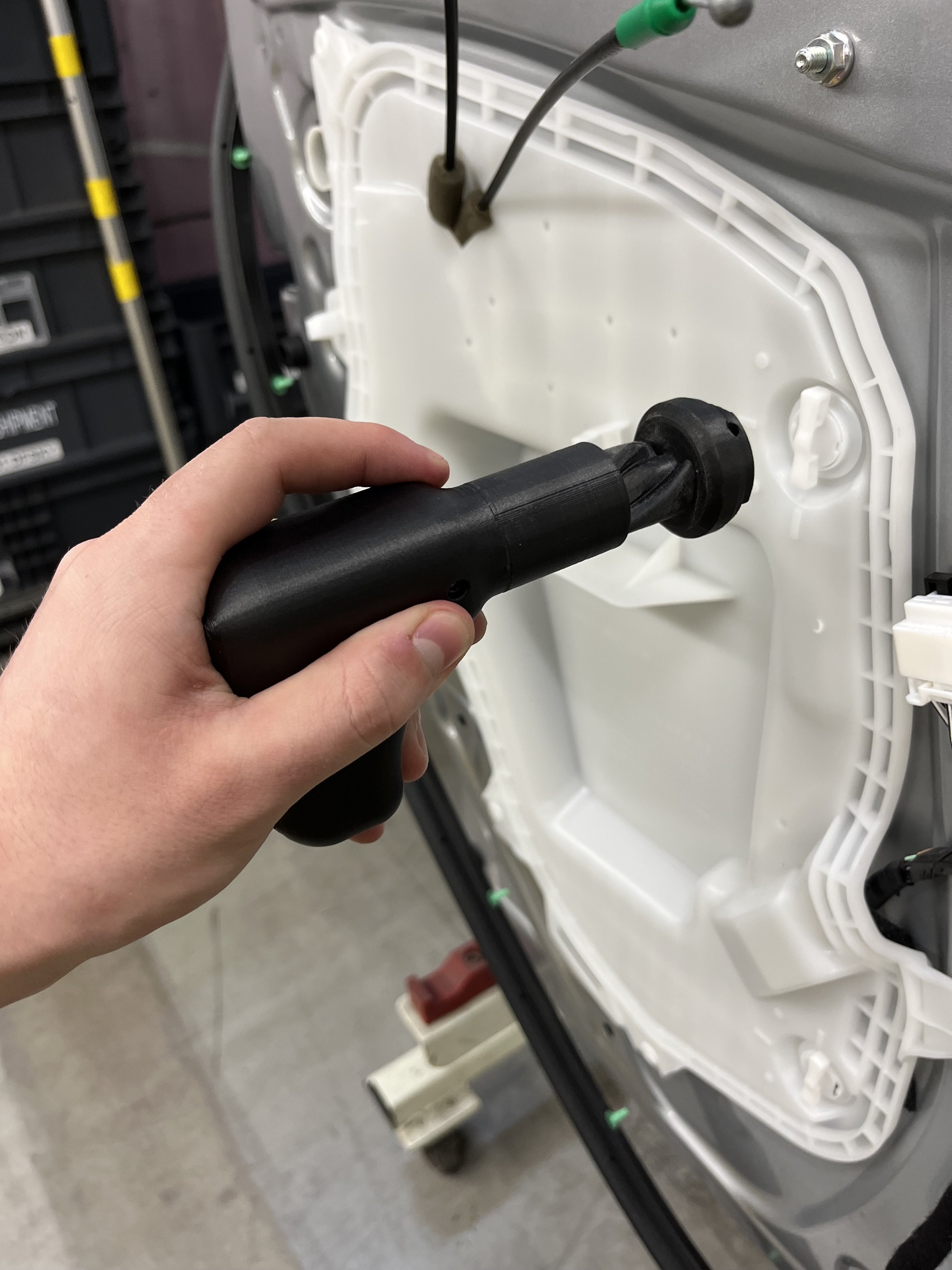
The tool worked as expected and had been continuously used for 3 weeks by the end of my internship.
The design was submitted for a patent application and shared with all global Toyota plants installing these clips. At the time of writing this, the tool is being trialed in TMMC South & North (Cambridge, Ontario, Canada), TMMK (Kentucky, USA), Toyota Takaoka Plant (Takaoka, Japan), and FAW Chengdu (Chengdu, China).